![]()
![]()
![]()
![]()
|
|
|
|
|
The External tab contains a list with diverse functions
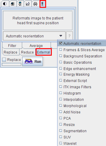
After selecting a function from the list and activating Run, a specific dialog window is opened to request the parameters needed for processing.
Add Noise
Adds Gaussian noise with zero mean and a standard deviation Sigma to the image.
Automatic Reorientation
Reformats the images such that they are displayed in the standard radiological head first supine position. This function requires that accurate patient positioning information is available.
Background
Methods to perform image background subtraction. The Thresholding selection contains Mean, Histogram, Optimal, and User Defined. The selected method determines a separation value, and all pixels below it will be replaced by the value specified with the New background value.
Basic Operations
Applies the numeric function configured as Operation to every pixel value, and uses the defined Replace value if the operation is mathematically undefined.
Edge Enhancement
Performs an edge enhancement operation based on different Methods: Inner gradient, Outer gradient, Gradient (Morphological) and Top hat. Structuring Elements of 2D SQUARE, 3D CUBE and 3D CROSS are available at the sizes of 3, 5, 7, and 9 pixels.
Energy Masking
Performs the masking of an image series based on the signal energy. The tool calculates the pixel-wise energy (sum of the squared signal values), determines the histogram of this energy map, and masks the specified percentage of pixels with lowest energy values based on a histogram analysis.
External Script
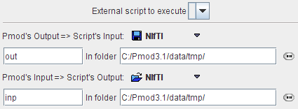
This tool allows running an external script, for example script that starts segmentation in SPM. External script should be placed in Pmod3.1/resources/extlibs/scripts folder. Pmod's output is considered to be script's input and is placed in the folder defined by the user. When the script is done Pmod loads the file that should be script's output from the specified folder.
Frames & Slices Average
Allows simple averaging within a time range and/or within a slice range. The number of generated slices/frames can be entered numerically.
Histogram
Calculates a histogram of all pixel values in the series. If Number of bars is enabled, the value range is divided into the specified number of equal intervals (eg. 128). With Bar resolution, the interval size is directly specified. The number of occurrences in each interval are counted and plotted as a curve. Note that the numeric values of the histogram can be exported using the context menu (right mouse button in curve are, then View Values).
Values below a Background level can be excluded by checking Ignore Background and specifying the Background level.
Interpolation
Methods for interpolating an image volume. With Number of Pixels the image volume can be sampled into a new number of pixels in each direction. With Pixel Size, a new size in each direction can be specified. The matrix size results from the division of the volume sizes by the pixel sizes.
With Transformation, a spatial transformation matrix (Manual, Rigid, Brain Normalization) can be applied to the image. If Reslice to original reference space is not checked, the transformation is applied with the current image resolution. Otherwise, it is resliced to the resolution of the Reference image during the calculation of the transformation.
ITK Image Filters
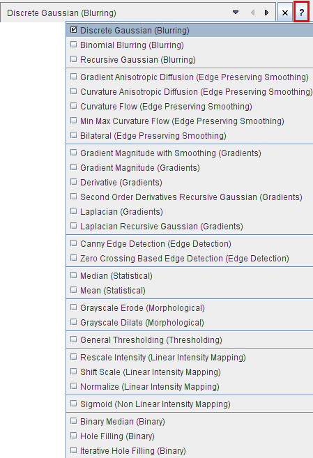
This tool provides an interface to 28 image filters provided by the ITK (Insight Toolkit) libraries. For each filter there is a short description which can be viewed with the ? button. The ITK is under an open-source BSD license which allows free usage. For more details please refer to the The ITK Software Guide.
Note: PMOD Technologies can not be held liable for permanent support of the ITK interface, nor for the performance of the provided libraries.
Morphological

Morphological operations process images based on shapes. Therefore Structuring Elements are required (2D SQUARE, 3D CUBE and 3D CROSS) of a certain size (3,5,7,9).
Erosion removes pixels on object boundaries, darkens small bright areas, and very small bright areas like noise spikes or small spurs might be totally removed.
Dilation adds pixels to the boundaries, brightens small dark areas, and very small dark spots might be totally removed.
Opening (Erosion-Dilation) removes small objects from an image while preserving the shape and size of larger objects in the image. It darkens small bright areas, and may entirely remove very small bright spots like noise spikes.
Closing (Dilation-Erosion) brightens small dark areas, and may entirely remove very small dark spots.
PCA (Principal Component Analysis)
No input is required for this function which is only applicable to dynamic series. The PCA performs a principal component analysis in the time domain. The generated series consists of the components sorted according to decreasing eigenvalues. The expectation is, that the PCA groups pixels with a similar uptake pattern over time in different components (representing "frames" in the generated series). The eigenvalues are written to the console.
Resize
Resize has two tabs.
Add Border serves for padding pixels around the current series. There is a symmetrical and an unilateral variant. The number of padded pixels can be specified for each direction separately, and there are different options for the filling value.
Get Box allows extracting a sub-volume of the current series (cropping). To this end, the new bounding box must be specified.
One way is to activate the Current Study button, which populates the Minimum and Maximum coordinates with that of the current study. Then the user can adjust the values numerically to get a sub-volume.
A convenient way is to base the extraction on the bounding box of a suitable VOI, which has been defined beforehand. Using the VOI button a VOI can be selected, its bounding box is read from the file and applied for sub-volume extraction. Note that the same functionality is also directly available in the VOI tool.
Segmentation
The Segmentation tool is a method for simple mask creation similar to the segmentation in the 3D tool. It opens the following dialog window.
The following segmentation methods available.
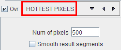
HOTTEST |
The HOTTEST PIXELS segmentation allows to get a 3D object of the (potentially disconnected) pixels with the highest values. The number of included pixels can be specified in the Num of pixels field.
|
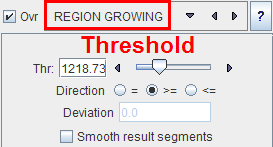
REGION |
Region growing is a method by which the user defines a starting point (seed) within the object of interest, and the algorithm tries to find all connected pixels which fulfill a certain criterion. After selecting REGION GROWING the following control elements appear.
The slider and the number field serve for defining the pixel value. Together with the Direction radio button the criterion for pixel inclusion is formed.
A preview of the result is shown in the Input display if the Ovr (Overlay) box is checked, for example after clicking into a brain tumor. To start the segmentation, navigate to a slice (in any direction) which shows the tissue of interest and click with the left mouse button onto a central point. Then adjust the criterion until the overlay indicates a promising segmentation. |
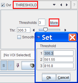
THRESHOLD |
The THRESHOLD segmentation is conceptually simple. All pixels above the threshold are included in the segment. Sometimes it is helpful to segment at several threshold levels at once. This can easily be realized by setting the number in the Thresholds field accordingly, select More, and enter the threshold values in the appearing Set dialog. In the example below, three segments of decreasing volume will be generated at thresholds 306.3, 561.55 and 816.8. During visualization, the user can show or hide each of the segments on demand.
|
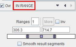
IN RANGE |
The IN RANGE segmentation is similar to the THRESHOLD method, except that an upper limit is also defined. This can be helpful to find objects with intermediate intensities. The complementary pixels which are outside the specified range can be obtained by checking the Inv box.
|
Otsu Threshold (ITK) |
"Another criterion for classifying pixels is to minimize the error of misclassification. The goal is to find a threshold that classifies the image into two clusters such that we minimize the area under the histogram for one cluster that lies on the other cluster's side of the threshold. This is equivalent to minimizing the within class variance or equivalently maximizing the between class variance." The ITK Software Guide.
With the mouse CT, Otsu with the settings above finds appropriate thresholds for the skeleton object and the soft tissue, as illustrated below.
|
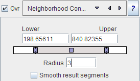
Neighborhood Connected (ITK) |
Neighborhood Connected is a region growing method with two criteria:
By the combination of these criteria small structures are less likely to be accepted in the region.
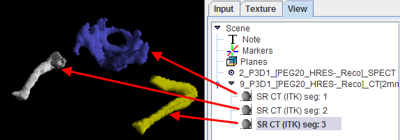
Multiple seed points can be specified by the use of markers.
and correspondingly multiple structures can be found at once.
|
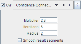
Confidence Connected (ITK) |
"The criterion used by the Confidence Connected method is based on simple statistics of the current region. First, the algorithm computes the mean and standard deviation of intensity values for all the pixels currently included in the region. A user-provided factor is used to multiply the standard deviation and define a range around the mean. Neighbor pixels whose intensity values fall inside the range are accepted and included in the region. When no more neighbor pixels are found that satisfy the criterion, the algorithm is considered to have finished its first iteration. At that point, the mean and standard deviation of the intensity levels are recomputed using all the pixels currently included in the region. This mean and standard deviation defines a new intensity range that is used to visit current region neighbors and evaluate whether their intensity falls inside the range. This iterative process is repeated until no more pixels are added or the maximum number of iterations is reached." The number of iterations is specified based on the homogeneity of the intensities of the anatomical structure to be segmented. Highly homogeneous regions may only require a couple of iterations. Regions with ramp effects, like MRI images with inhomogeneous fields, may require more iterations. In practice, it seems to be more important to carefully select the multiplier factor than the number of iterations. However, keep in mind that there is no reason to assume that this algorithm should converge to a stable region. It is possible that by letting the algorithm run for more iterations the region will end up engulfing the entire image. The initialization of the algorithm requires the user to provide a seed point. It is convenient to select this point to be placed in a typical region of the anatomical structure to be segmented. A small neighborhood around the seed point will be used to compute the initial mean and standard deviation for the inclusion criterion."
|
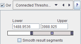
Connected |
Connected Threshold is a region growing method with the criterion that (similar to the IN RANGE method) the included pixel must have values between a Lower and and Upper threshold.
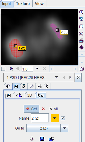
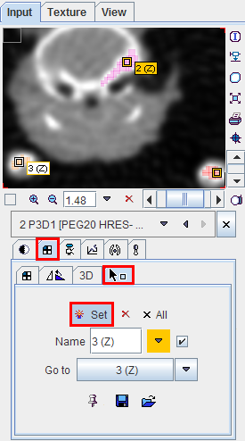
As usual with region growing methods, the user has to specify a seed point by clicking into the image. The ITK region growing methods are particular in that multiple seed points can be specified at once by the use of markers as illustrated below.
Once the markers tab has been activated and the Set button enabled, a marker is created as a seed point for each clicking into the image. When the segmentation is started, the region growing with the specified value range is performed from each marker.
|
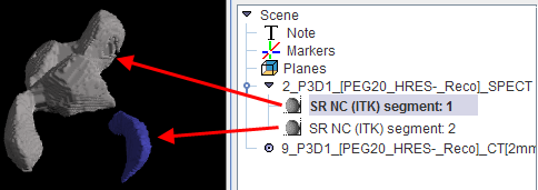
After specification of the segmentation method and its parameters, the segmentation can be started with the Run Segmentation button. The result is shown in the right image display port. Note that if the study is dynamic, an additional box All Frames appears. If it is checked, segmentation will be performed for all frames separately, otherwise with the frame which is currently shown.
The segmentation result can be used in different ways:
Wavelet
De-noising using Daubechies or Battle-Lemarie wavelets. The methods operate in the plane, the entire volume, or in the plane over time.