![]()
![]()
![]()
![]()
|
|
|
|
|
Volumetric images can be displayed in many different ways in the PMOD tools. The layouts are accessible by the second control tab, on the first sub-tab Layout.

Slice Orientation
The buttons in the first row allow defining the orientation of the displayed images.
|
z-Plane: Corresponding to the major slice orientation of the loaded data. Usually axial images. Keyboard shortcut: CTRL+Z. |
|
y-Plane: Usually the coronal images. Keyboard shortcut: CTRL+Y. |
|
x-Plane: Usually the sagittal images. Keyboard shortcut: CTRL+X. The x-plane image can be shown in two different ways depending on the modifier buttons.
|
|
Orthogonal Planes: Layout showing three orthogonal slice images. The intersection point can be moved by clicking into the images. |
The plane orientation can rapidly be switched by first activating an image (click into image), and then entering the keyboard shortcut.
The direction z, y or x indicates the normal to the shown plane shown. The y-, x- and orthogonal buttons are not active if the study is planar only and can thus not be resliced in an other than the original direction.
Tiling Layouts
The second and third rows allow configuring the number of images shown concurrently.
If the radio button in the second row is enabled, a dedicated row x column layout is used for the different orientations.
This is particularly helpful for a whole-body study where the coverage in z is much larger than in the other directions. The definition of the layout per plane orientation is done in the particular tool configuration ![]() .
.
Otherwise, if the radio button of the third row is enabled, the same layout is applied for all orientations and the arrangements are accessible through the selection
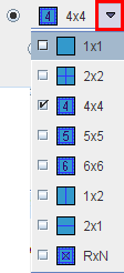
Keyboard shortcuts allow to quickly switch arrangements. After clicking into an image enter
To change from a tiling layout to 1x1 just click on the image to be enlarged holding down the CTRL key. To change back to the multi-image layout just CTRL and click once more.
The radio button in the fourth row is only applicable for image tiling with dynamic studies.
![]()
If the radio button is in the position of
Orthogonal Layout
If the orthogonal layout is selected, three quadrants show the orthogonal slice images intersecting at the point indicated by the cross centered in the blue slice indication lines (triangulation point). As soon as the user clicks into an image, the images are updated by the slices intersecting at that new point.
The fourth quadrant is available for different information. It can be configured by activating the button located in the upper left corner of that quadrant, indicated in red in the screen capture above. A dialog appears
which lets choose between an Empty quadrant, a Locator display showing the slices location schematically, and a MIP (Maximum Intensity Projection). Note that there is a marker in the MIP image, which indicates the current slices intersection. It can be moved, and the slice images will follow. This function may be helpful to track vessels showing up highlighted in the MIP.
Rotations and Mirroring
Image reorientation operations such as mirroring and rotations can be done using the buttons in the dedicated pane.
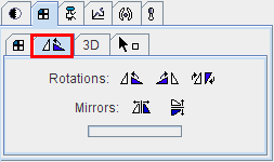
If the display is in the orthogonal viewing mode, first activate the appropriate plane by clicking onto the corresponding image (holding down the CTRL key avoids new reslicing), and then activate the appropriate button.
Note: For data with enough information about patient positioning PMOD will keep track of patient orientation and update the annotations accordingly.