![]()
![]()
![]()
![]()
|
|
|
|
|
The creation of a CFD case can be started activating the Create CFD Case green button. A dialog window opens as illustrated below:
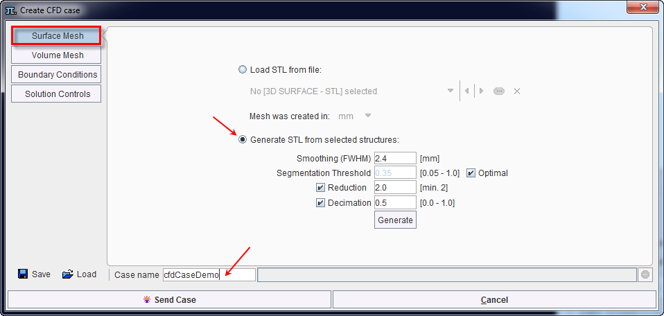
It requests a Case name definition for the CFD case. Initially, only the Surface Mesh entry on the left side menu is active as STL structures are requested to create a CFD case.
Surface Mesh
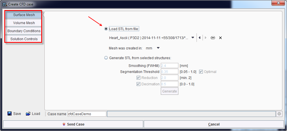
There are two possibilities to provide STL structures for modeling:
Smoothing (FWHM) |
It is a Gaussian filter and allows smoothing the data before creating the STL structure. The default value corresponds to the pixel size in the data. |
Segmentation Threshold |
All pixels with the value above the threshold are included in the segment. When the Optimal checkbox is enabled the threshold will be calculated automatically such that the volume of selected data is conserved. |
Reduction |
If enabled, allows creating simplified mesh based on data simplification. The defaults value is 2 and is representing the smallest value to be defined. Initially, the program will use this number and multiply the pixel size of the data with this value. Finally, the mesh will be generated on the new data. It is a faster procedure and the results will consist in mesh being less precise. Please note that if only this checkbox is enabled the generated files will be bigger and change in topography of the mesh will occur. |
Decimation |
Allows simplifying mesh. Please note that in this case the simplification procedure is done after the mesh is created. It is a slow procedure which generates smaller files. Decimation only changes the number of STL nodes, particularly the vertices of the surface mesh. However, no change in the mesh geometry occurs, preserving thus the mesh topology. |
Generate |
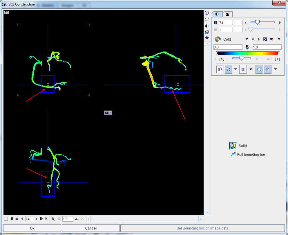
The activation of this button starts the mesh calculation. Upon completion a dialog opens showing the 3D preview of the mesh and allowing the definition of the Full bounding box as illustrated below:
The manipulation of the bounding box allows setting cutting planes. The result would be a surface mesh consisting of the "original" body and flat surfaces on the cutting planes that are just adjacent to the "original" body mesh. The flat surfaces are useful to define the boundary conditions. Confirm with OK to return to the Create CFD Case interface. Consequently, the menu on the left hand side is becoming active. Note that for the CFD modeling only a small part of the selected element should be enclosed within the box. |
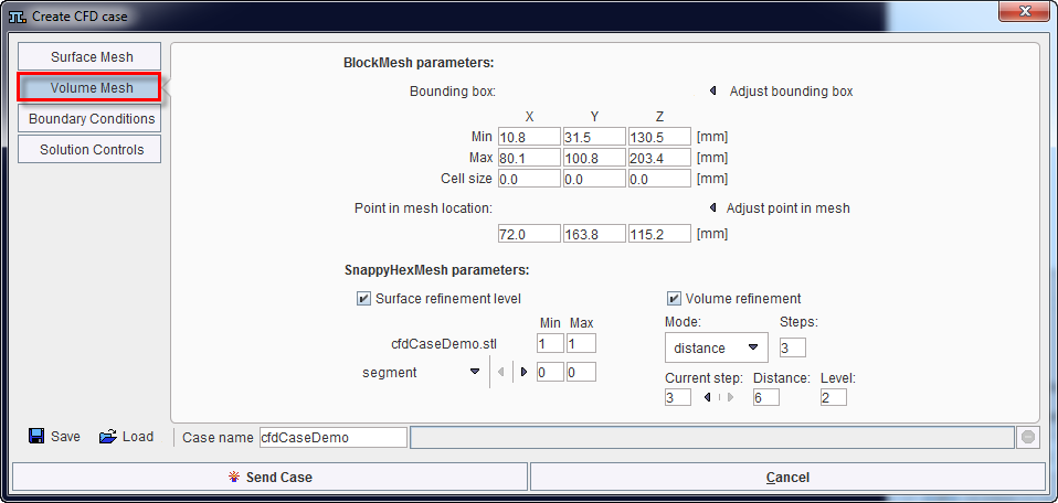
Volume Mesh
Once the surface mesh is created the user can proceed with the creation of the volume mesh.
The Volume Mesh interface is organized in two main sections:
The Volume Mesh setting parameters are summarized in the table below:
Bounding box |
|
Point in mesh location |
Is representing any point inside the surface mesh. This point is used only to determine whether "sculpting" of the volume mesh should take place inside or rather outside the surface mesh. Please note that Adjust point in mesh is grayed out when the surfer mesh is loaded from an external STL file. |
Surface refinement level |
Allows refining the mesh in the neighborhood of particular surfaces. Please note that this procedure affects the volume nearby. If enabled, the Min and Max level need to be specified. When a value of 1 is set there will be no refinement calculation. In case the values are different, the refinement will be applied nearby the whole surface. Additionally, particular surfaces can be selected: segment or cutting planes. |
Volume refinement |
Allows defining how many times the volume mesh inside the whole volume will be refined. If the check box is enabled, there are three Modes for the refinement procedure:
- step 1: distance 2 and level 6, - step 2: distance 4 and level 4, - step 3: distance 6 and level 2. It is important that levels are ordered starting from the nearest one. |
Boundary Conditions
Boundary conditions for two physical variables can be defined for each surface belonging to the surface mesh: pressure and velocity.
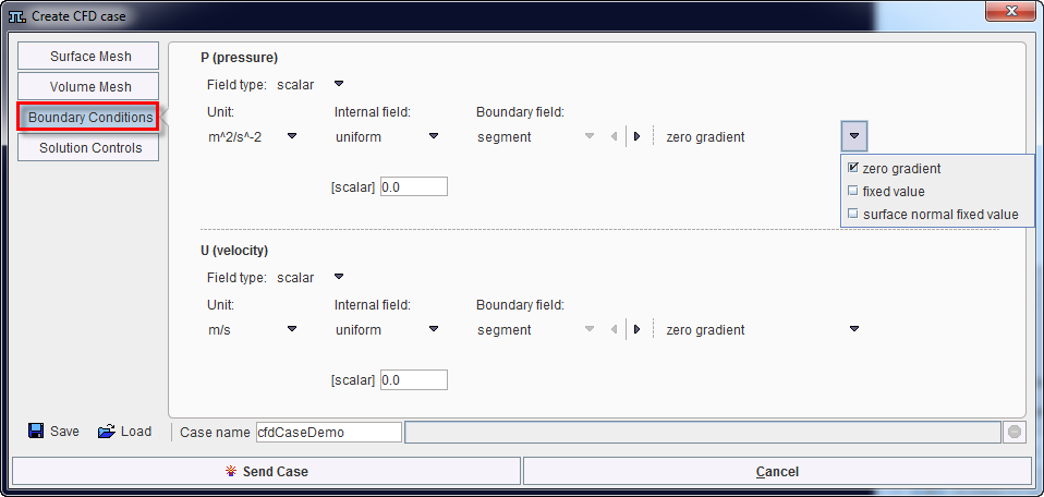
The settings available in this interface are:
Field type |
Allows selection of a scalar or vector type. |
Internal field |
If uniform entry is selected means that all cells of the volume mesh will have the same value. When non-uniform is selected, a file needs to be provided using the Load button. |
Boundary field |
Allows determining boundary conditions on the boundary: walls and cutting planes. Three options are available:
|
[scalar] |
Is an integer value and need to be specified in the dedicated field. |
Unit |
Allows defining the specific unit for the P(pressure) and U(velocity) respectively |
Solution Controls
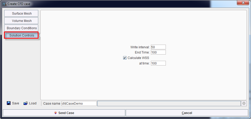
The following settings are available:
Write interval |
Allows defining how often the OpenFOAM solver should write down the results. |
End Time |
Allows defining the iteration number of the solver. The number is representing the iteration for the steady state simulations. |
Calculate WSS |
Allows calculating the wall share stress for the particular iteration number specified in the at time field. |
The easiest way to store all the settings done for the project is using the Save button below the left side menu. All the information will be saved in a .cfdCase file which can be easily retrieved using the Load button.
Finally, to send the CFD case to the OpenFoam interface activate the Send Case button.