![]()
![]()
![]()
![]()
|
|
|
|
|
During the assignment of segments to organs it may be helpful to relate the information in the image display with an anatomical whole-body atlas. The PSEG tool includes a 3D rendering of the Digimouse Atlas which is only available if the PMOD license contains the P3D rendering option. In this case the corresponding  button in the lateral taskbar is active and launches the tool as illustrated below.
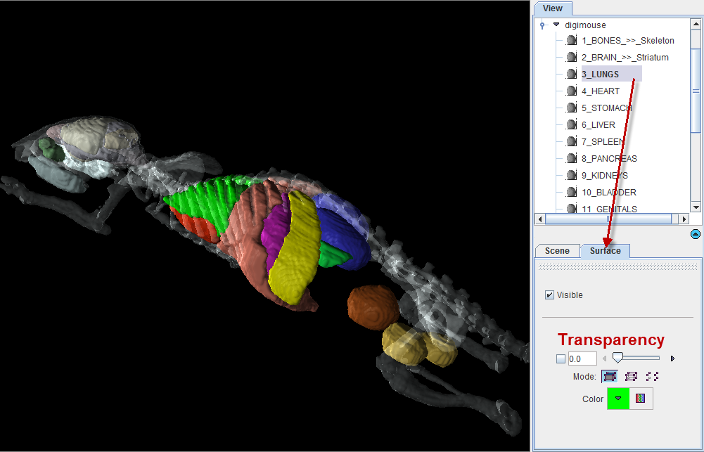
Note the organ list in the View panel to the right which allows selecting individual objects and changing their representation. In the example above, the 3_LUNGS object is selected, with the corresponding Surface panel giving access to its properties. For instance, by removing the Visible check the lungs can be hidden from the rendering. Note that multiple objects can be selected and a property such as the transparency changed for all of them at once. Please refer to the PMOD 3D Rendering Tool Guide for more information about the renderings options.
Note: The 3D Digimouse window can remain open while assigning the segments. After hiding irrelevant structures it is recommended to reduce the window size and hide the control area with the ![]() button in the lateral taskbar.
button in the lateral taskbar.
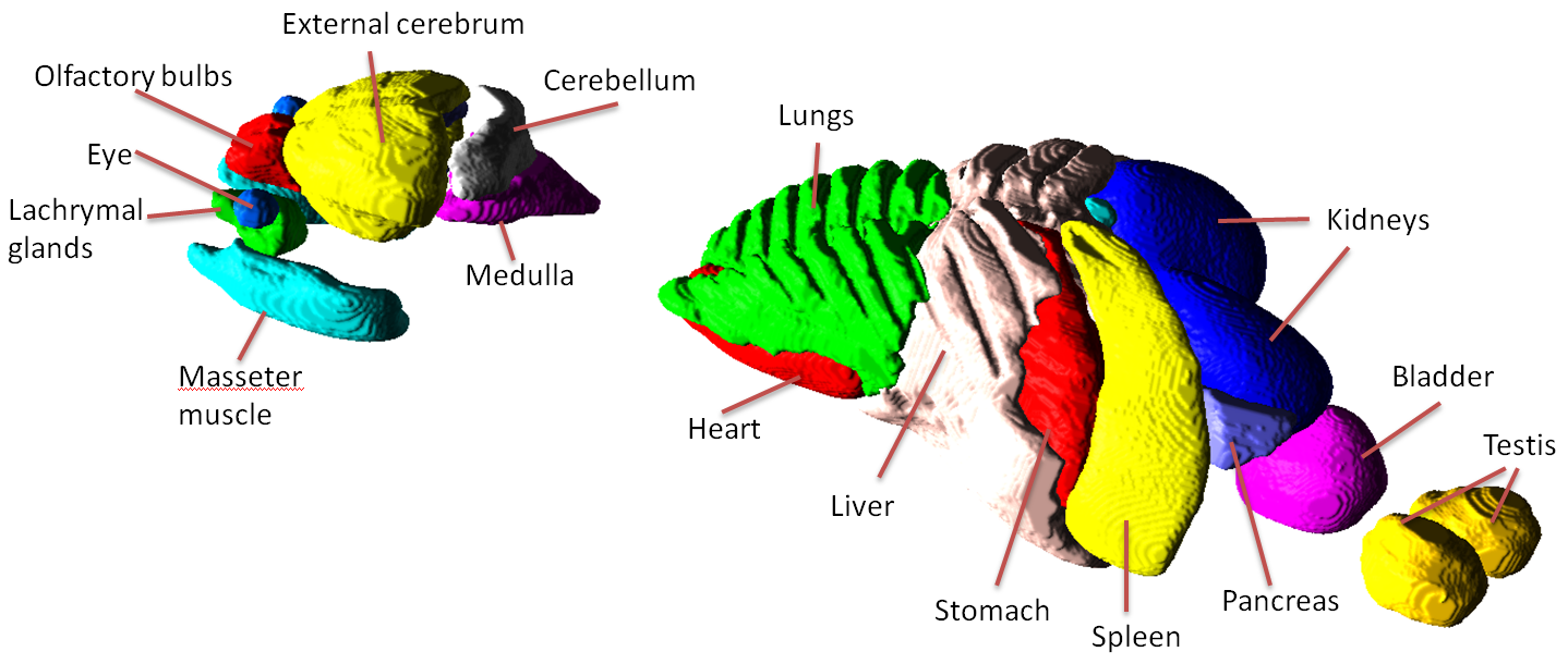
The structures available in the Digimouse phantom are illustrated below.
The VOIs created by the segment assignment process are regular PMOD contour VOIs which can be adjusted in many ways. For instance, if the segmentation produced two complementary parts of a structure, their VOIs can easily be merged into a single VOI.
Manual VOI Addition
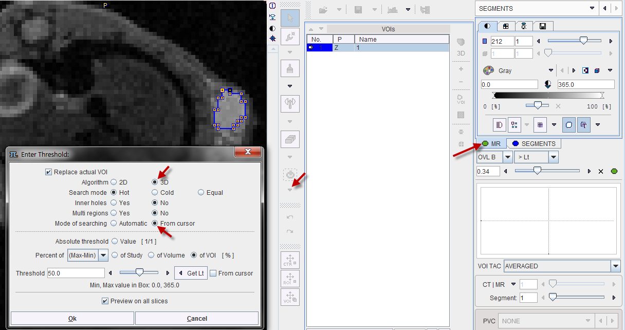
VOIs can also be added in a completely manual manner. In the example data set, for example, there is a bright part in the MR image which does not take up FDG.
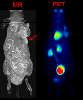
In the present situation, a VOI can be obtained from the MRI image using the iso-contouring tool as illustrated below. First, the MR image tab is selected to direct the iso-contouring operation to the MR image content, not the SEGMENTS. Then, the iso-contouring is started. The parameters are set to 3D with Multi regions off, to create a single compact VOI. Setting the Mode of searching to From cursor will ensure that VOI creation starts at the location where the user clicks. The iso-contour is shown in the image, and the contouring level may be adjusted by the Threshold setting.
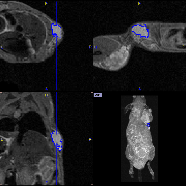
After closing the dialog window with Ok, the contouring result is shown as illustrated below, and the VOI can be labeled.
Morphological Operations
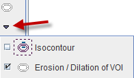
Morphological operations support convenient functions for modifying the created VOIs, such as shrinking, growing, removing holes and single pixels. Please select the VOI to be modified in the list, then activate the Erosion/Dilation function from the VOI tools area.
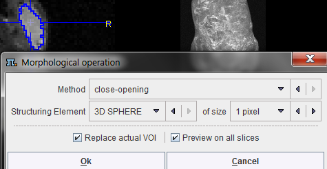
A dialog window appears which offers a list of Methods with corresponding Structuring Elements and their size. The changes to the VOI are immediately reflection when configuring the operation. Note that the result may replace the existing VOI, or added as a new VOI.
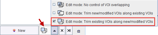
Non-overlapping of VOIs
In order to avoid the overlapping of VOIs, which causes problems with the partial-volume correction, the VOI Edit mode is pre-configured accordingly.
If VOIs are created by the merging of existing VOIs, please make sure that the original VOIs are removed.
Palette of VOI Tools
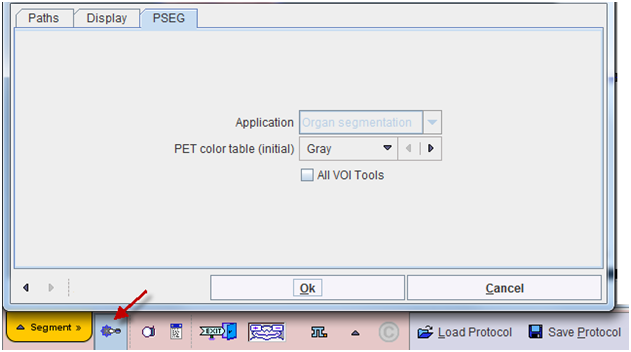
Per default only a subset of the PMOD VOI tools is available in PSEG. To be able to use the full VOI functionality please enable All VOI Tools in the configuration.