![]()
![]()
![]()
![]()
|
|
|
|
|
In the example below, the Heart HR model is used. For each entry in the model tree a property of HU was defined as explained previously.
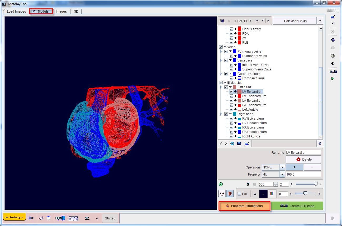
To start the simulation activate the Phantom Simulations button. A new dialog window opens as illustrated below:
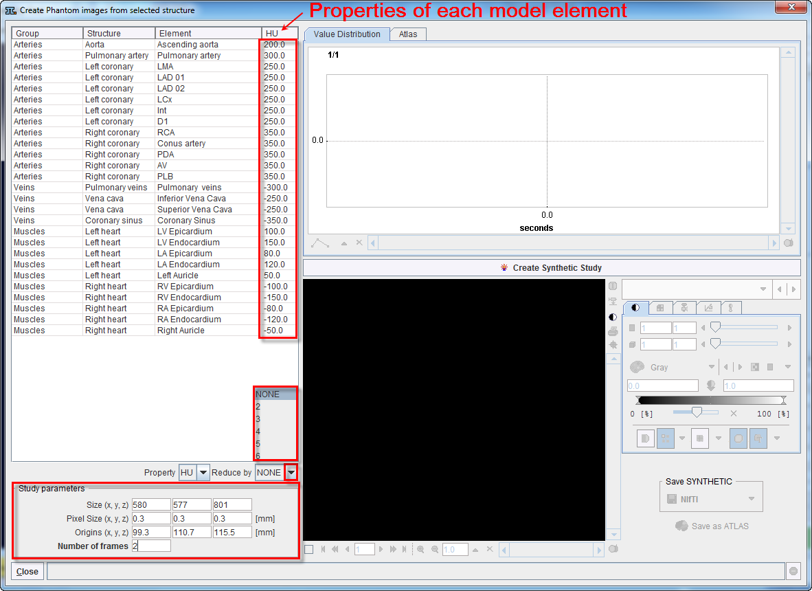
The window consists of four main areas:
Create Synthetic Study
Activate the Create Synthetic Study button to start generating the phantom image based on the definition of each elements property. The results of the simulation are shown on the lower right section as illustrated below:
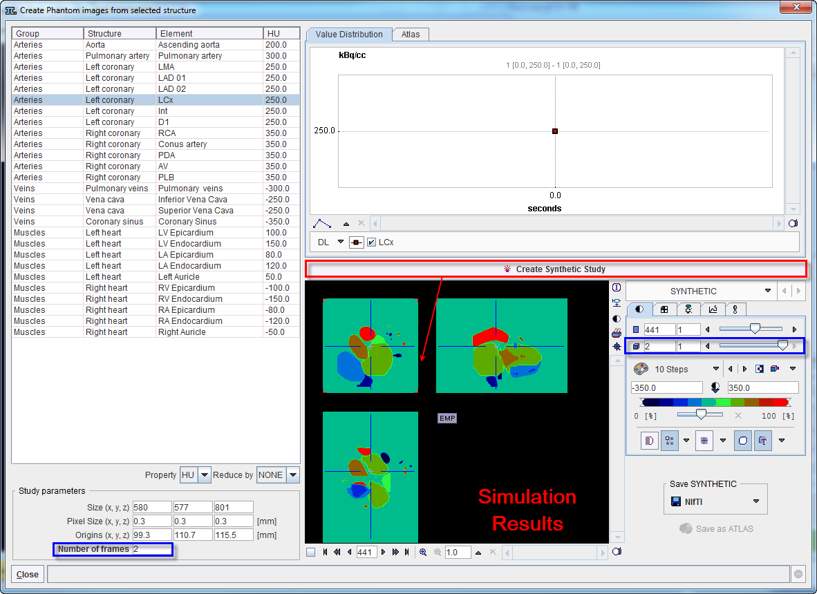
Save Synthetic Study
The simulated phantom image can be saved in the Save SYNTHETIC section. Detail information about image saving is available in the PMOD Basic Guide.
In addition, the simulated data can be saved as an Atlas. To achieve this the Atlas tab need to be selected in the upper right section. Consequently, the Save as Atlas button is becoming active as illustrated in the following capture:
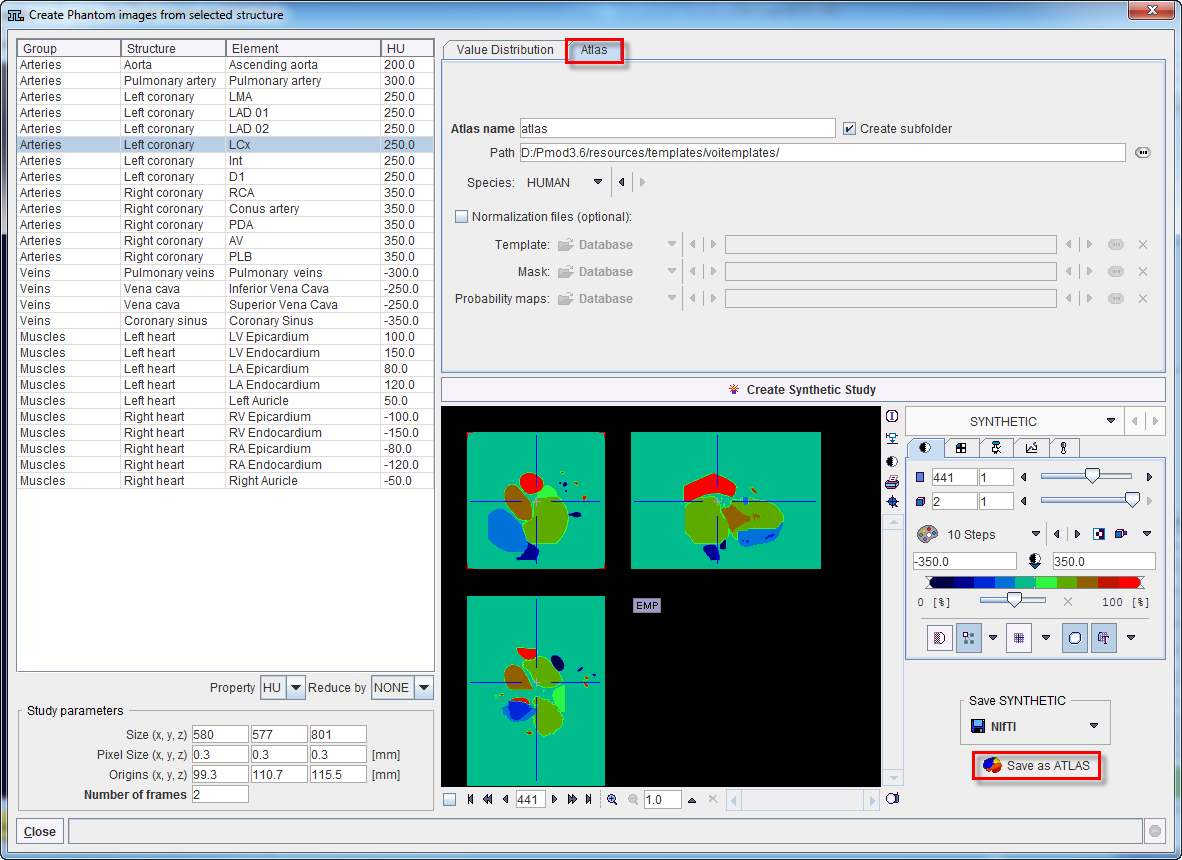
An Atlas name is requested and can be defined in the dedicated text field. Using this name a subdirectory is created in the Path directory which defaults to resources/templates/voitemplates, but which can be changed. The Species selection allows tagging the VOI atlas so that it will be shown in the corresponding context.
An image series is generated which encodes each element (VOI) pixel as an appropriate numeric label and saved in NifTI format. Additionally, a text file is created for the mapping of the numeric labels to VOI names.
Optionally, files for the spatial normalization can be defined for the template. To this end enable the Normalization files (optional) box and select a Template file and a Mask file, which will be used for the deformable registration.
When a brain phantom is simulated a Probability maps file should be selected. This encodes the Grey matter, white matter and CSF probability maps as a dynamic data set. In this case, a normalization folder is created with the normalization image in NifTI format (norm_template.nii). It also contains a mask sub-folder for the mask image (mask.nii), and a tpm folder for the tissue probability map (tpm.nii). These files allow applying the Probability Maps Normalization available in PMOD for brain studies.