![]()
![]()
![]()
![]()
|
|
|
|
|
The VOIs page is illustrated below. This page serves for outlining volumes-of-interest directly on the fused images and supports the definition of the models structure.
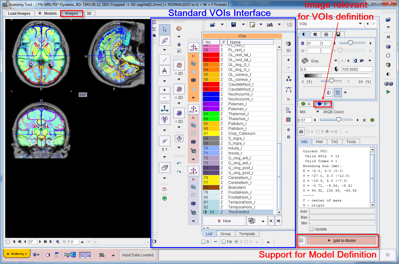
VOI Definition
The standard VOI options are available for the VOI creation. Please refer to the PMOD Base Functionality Guide for explanations of the VOI functionality. The only distinctive thing to consider is that the series selected on the tab to the right (A or B) is relevant for VOI definition.
Add VOIs to the Model
In the example below the Hammers-N30R83 brain VOIs were projected to the patient space. Note that brain VOIs are structurally organized in a tree on the Group tab of the VOI editing page. Please refer to the PMOD Neuro Tool Guide for explanations related with tree organization of brain VOIs.
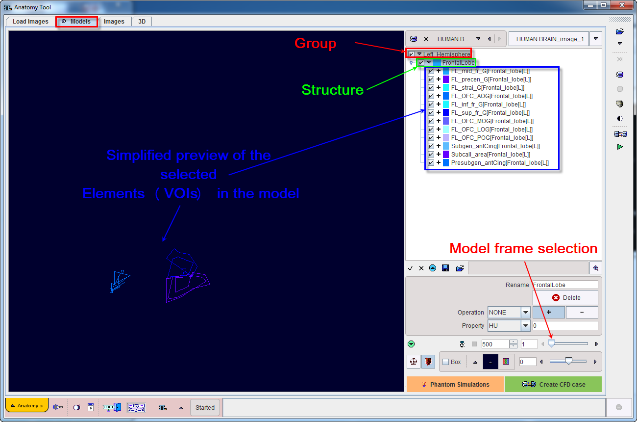
To start adding VOIs to the model the Group tab is selected as illustrated below:
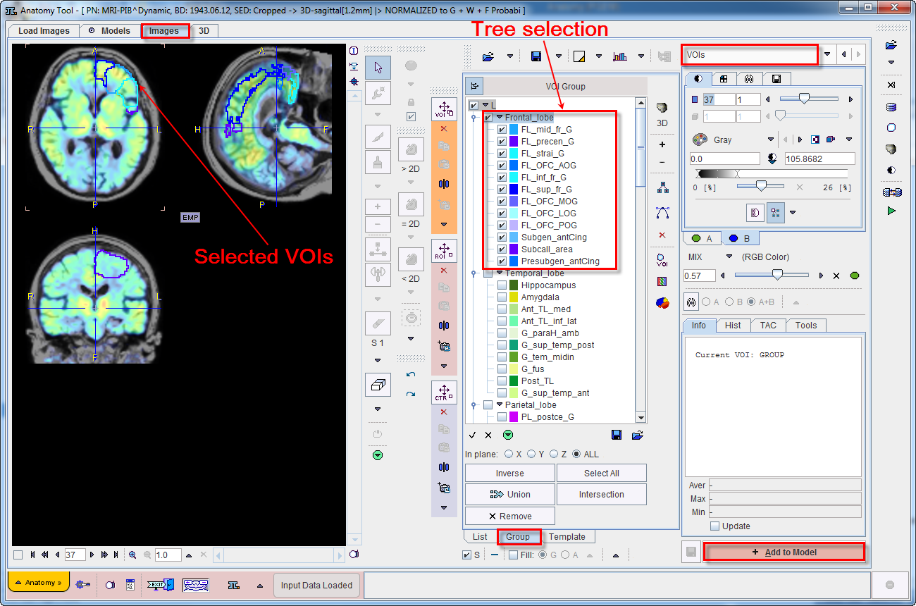
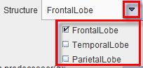
The structures belonging to the Frontal_lobe of the left L branch are selected. Note that the structures of interest are the ones with checked boxes to the left of their color code. The currently selected VOIs can be added to the model activating the Add to Model action button. A dialog window opens as shown below:
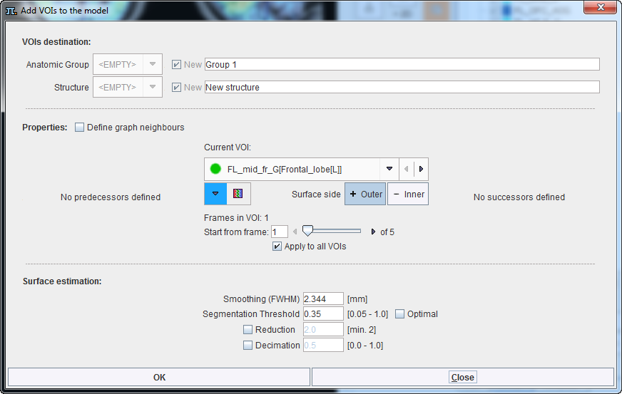
The window is organized in three main sections:
VOIs Destination
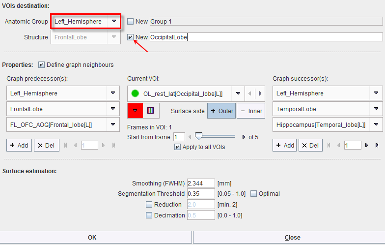
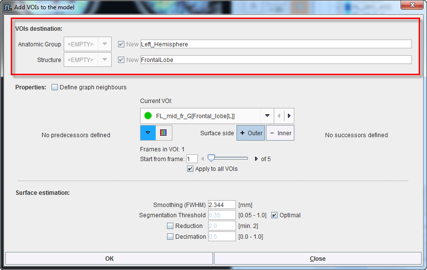
The VOIs destination section requires definitions for the Anatomic group and Structure. When VOIs are added to the model for the first time, these settings are <Empty> and New names need to be provided in the dedicated field. To this end, the Left_Hemisphere and the FrontalLobe were set as Anatomic Group and Structure respectively.
The settings available in this section are summarized in the table below:
|
Allows defining model Anatomic Group to which the VOIs will belong. To define a new Anatomic group the New checkbox has to be enabled and the name specified in the dedicated text filed. Confirm and add the entry to the list with the Enter button on the keyboard. The drop down arrow allows selecting among the currently available Anatomic group. |
|
Allows defining model Structure to which the VOI will belong. To define a new Structure the New checkbox has to be enabled and the name specified in the dedicated text filed. Confirm and add the entry to the list with the Enter button on the keyboard. The drop down arrow allows selecting among the currently available Structure. |
To add the VOIs available in the Current VOI list to the model the OK button has to be activated. Make sure to keep the default settings for the Properties and Surface estimates. The result is illustrated below:
Similarly, the OccipitalLobe, ParietalLobe, TemporalLobe and DeepNuclei Structures were added to the Left_Hemisfere Group. The model tree structure is illustrated below:
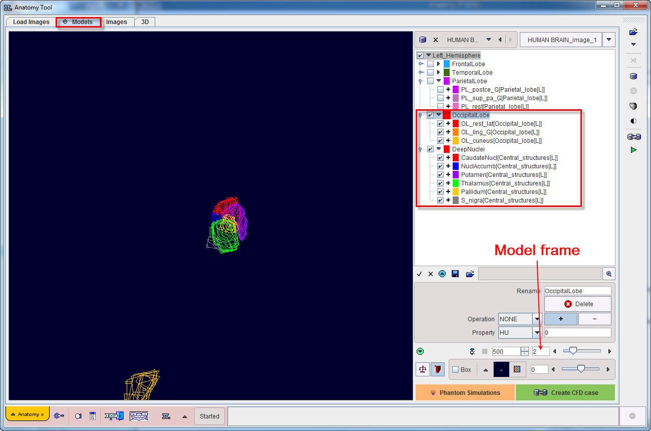
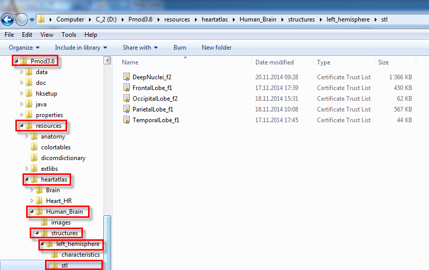
For each Group entry in the model tree the program automatically creates a folder with the same name. The destination of this folder is the structures folder of the model folder. The model folder location is defined in the Structural Model Path section in the configuration settings. The folder content of the Left_Hemishere group entry on the model tree is illustrated below:
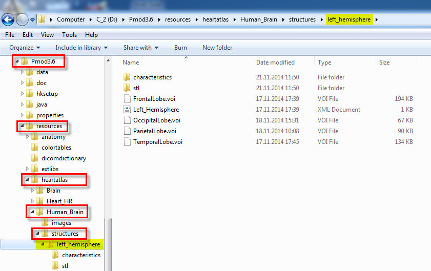
It contains:
Properties
While adding VOIs to the model, various Properties can be defined in the dedicated section. The properties settings are summarized below:
|
Allows changing or editing the color of the VOI(s) to be added to the model structure. |
|
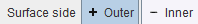
Allows setting the VOI(s) as an Outer or Inner surface |
|
When enabled applies the same properties to all the VOIs available on the Current VOI selection list. Please note that more than one VOI at the time can be added to the model. |
|
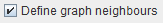
If enabled allows defining predecessor(s) and successor(s) to the Current VOI selection as illustrated below:
In the example above a new Structure (OccipitalLobe) is added to the Left_Hemisphere Anatomic Group. The OL_rest_lat[Occipital_lobe[L]] is selected as Current VOI. The VOI will appear on the frame number 1 as set in Start from frame field. The following Graph predecessor was defined for the Current VOI:
Similarly, the Graph successor was defined:
Please note that:
|
Frames in VOI |
Provides information related with the VOI type:
|
Start from frame |
Allows setting the frame in the model where the VOIs will be added. Please note that in case of dynamic VOIs the number indicates the starting frame of appearance in the model. Please note that the frame number for the model was defined in the Create New Model step. |
Surface Estimation
The Surface estimation section allows defining characteristics for the STL model structures. The settings are as follows:
Smoothing (FWHM) |
It is a Gaussian filter and allows smoothing the data before creating the STL structure. The default value corresponds to the pixel size in the data. |
Segmentation Threshold |
All pixels with the value above the threshold are included in the segment. When the Optimal checkbox is enabled the threshold will be calculated automatically such that the volume of selected VOIs is preserved. |
Reduction |
If enabled, allows creating simplified mesh based on data simplification. The defaults value is 2 and is representing the smallest value to be defined. Initially, the program will use this number and multiply the pixel size of the data with this value. Finally, the mesh will be generated on the new data. It is a faster procedure and the results will consist in mesh being less precise. Please note that if only this checkbox is enabled the generated files will be bigger and change in topography of the mesh will occur. |
Decimation |
Allows simplifying mesh. Please note that in this case the simplification procedure is done after the mesh is created. The defined value should between 0 and 1. It is a slow procedure which generates smaller files. Decimation only changes the number of STL nodes, particularly the vertices of the surface mesh. However, no change in the mesh geometry occurs, preserving thus the mesh topology. |